

 English


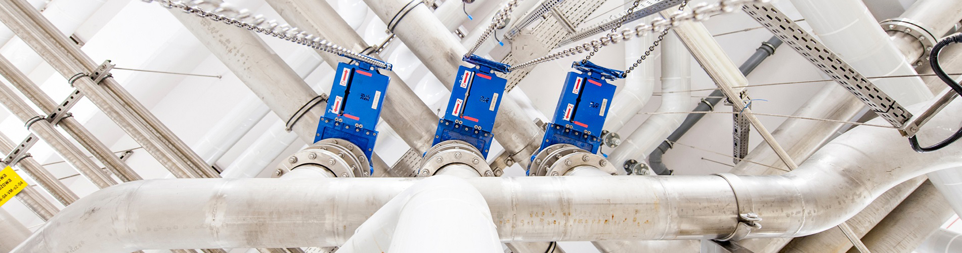
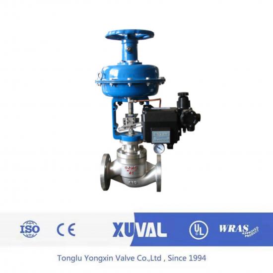
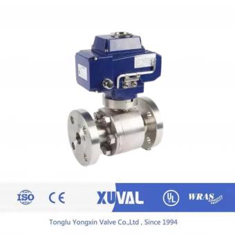
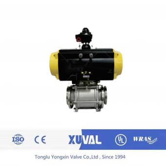
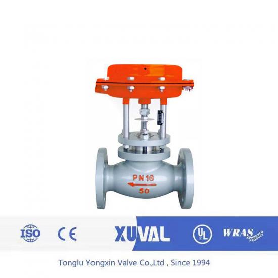
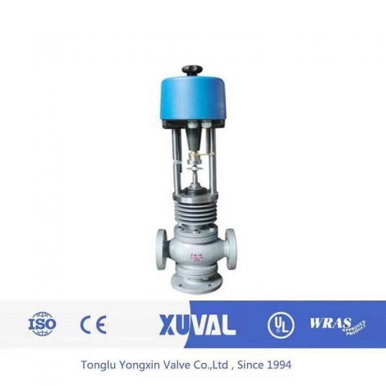
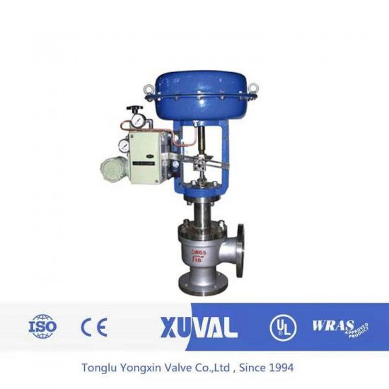
Pneumatic diaphragm direct single seat regulating valve, pneumatic three-way regulating valve, electric three-way diversion regulating valve, pressure regulating valve, also known as regulating valve, flow control valve, flow controller, dynamic balance valve, flow balance valve, is an intuitive and simple flow regulating control device. The regulating valve structure is composed of an electric actuator or pneumatic actuator and a valve body.
Item NO.:
XUVAL33-344Lead Time:
45 DaysProduct Orgin:
CHINABrand:
XUVALShipping Port:
ShanghaiPayment:
100%TTColor:
silveryMOQ:
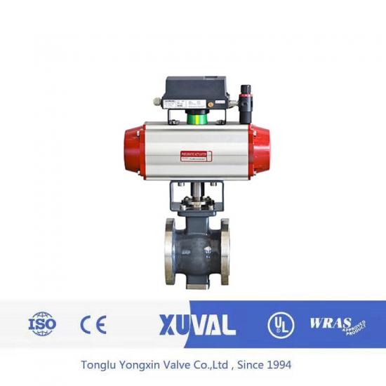
1There are two main types of straight stroke: straight single seat and straight double seat. The latter has the characteristics of high flow capacity, low imbalance force, and stable operation, so it is usually particularly suitable for situations with high flow rate, high pressure drop, and few leaks. The angular stroke mainly includes V-shaped electric regulating ball valve, pneumatic diaphragm cut-off valve, eccentric butterfly valve, etc.
The application of flow control valves in the pipeline network can directly set the flow rate according to the design. The valve can automatically eliminate the residual pressure head and flow deviation caused by pressure fluctuations in the pipeline under the action of water, and maintain the set flow rate regardless of changes in system pressure. These functions of the valve enable the flow regulation of the pipeline network to be completed in one go, transforming the network adjustment work into simple flow distribution and effectively solving the hydraulic imbalance of the pipeline network. The flow control valve is mainly used in centralized heating (cooling) and other water systems to distribute the flow of the pipeline network as needed, eliminate hydraulic imbalance in the water system, solve the problem of uneven heating and cooling, and save energy by 15% -20%.
Technical parameters:
1、 The characteristics of small flow control valves
The so-called small flow regulating valve, as the name suggests, is a regulating valve with very low flow capacity.
The flow capacity of a valve is a valve capacity indicator under unified conditions. In our country, it is represented by the value of C. Its definition is: when the valve is fully open, when the pressure difference before and after the valve is 1 kilogram/cm2, and the medium weight is 1 gram/cm3, the medium mass flowing through the valve per hour (m3/hour). For incompressible fluids, in a sufficiently turbulent state (when the Reynolds number is large enough, for water Re>10 5; for air Re>5.5 × 10 4)
In the formula:
△ p - Pressure difference before and after valve (kg/cm2) Υ-- Medium weight (g/cm3)
Q - Medium flow rate (m3/hour)
The United States and other countries use C, where the value represents the flow capacity of the valve. The internationally recognized I, E, and C standards for electricity mainly use Av values to represent the flow capacity of valves. The conversion relationship between the three is as follows:
C=1.17 C Cv=10 6/24Av C=10 6/28Av
The flow capacity of a valve only depends on the structure of the valve itself. When calculating the required valve flow capacity, attention should be paid to the significant differences in the flow state inside the valve due to different media or flow conditions.
In low flow conditions, especially when working with viscous fluids and low pressure, the main constraint of the fluid is often laminar or a mixture of laminar and turbulent flow. When laminar flow occurs, there is a linear relationship between the flow rate of the medium passing through the valve and the pressure difference before and after the valve. In laminar and turbulent mixed states, as the Reynolds number increases, even if the pressure difference remains constant, the mass of the medium flowing through the valve will also increase. In complete turbulence, the flow rate does not change with the change of Reynolds number. Nevertheless, choosing a small flow control valve still relies on traditional methods
The method and calculation formula are used. However, its calculated value deviates greatly from the actual value. According to the data, when Cv=O.01 or below, it is only used as a capacity indicator and has reference significance. The actual circulation capacity should be determined based on experience.
As the flow capacity decreases, the adjustable ratio of the valve will decrease. But at least it can guarantee a flow rate between 10:1 and 15:1. If the adjustable ratio is too small, it will be difficult to adjust the flow rate.
When valves are used in series, as the opening changes, the pressure difference before and after the valve also changes, which causes the working characteristic curve of the valve to deviate from the ideal characteristics. If the pipeline resistance is high, the linearity will become a fast opening characteristic and lose the ability to adjust. The equal percentage characteristic will become a straight line characteristic. Under low flow conditions, due to minimal pipeline resistance, the distortion of the above characteristics is not significant, and the equivalent percentage characteristic is actually unnecessary. From a manufacturing perspective, it is also impossible to generate an equal percentage of side shape below Cv=O.05. Therefore, the main problem with small flow valves is how to control the flow within the required range.
From an economic perspective, users hope that a valve can be used for both interception and regulation simultaneously. But for regulating valves, the main purpose is to control the flow rate, and closing is secondary.
Introduction to Features:
The pneumatic diaphragm single seat regulating valve has a valve core and a valve seat inside the valve body, which has the characteristic of small leakage. This valve has a large unbalanced force and allows for a smaller pressure difference compared to a double seat valve. When operating under high pressure and with a large diameter, it is best to equip it with a valve positioner. Valves with a nominal diameter of ≥ 25mm have a dual guide structure. As long as the connection position between the valve stem and the valve core of the pneumatic diaphragm single seat regulating valve is changed, it can achieve pneumatic opening or closing.
A single seat pneumatic diaphragm single seat regulating valve has a valve core and a valve seat inside the valve body. As long as the connection position between the valve stem and the valve core is changed, air opening or air closing can be achieved.
Main features: Equipped with PSL intelligent straight stroke electric actuator, it has a small volume, complete specifications, light weight, high thrust, convenient operation, no adjustable potentiometer, reliable single seat regulating valve (10 pieces), high pressure, and low noise. The PSL electric actuator adopts a modular design with self diagnostic function, making it very convenient to use and adjust.
There is a digital display window where you can see the control signal value and valve position value.
PSL intelligent electric actuator function: fault diagnosis, alarm and protection function with broken control signal. When the signal is disconnected, the actuator can be turned on or off; Or close; Or maintain; Or set at any position between 0 and 100%. And with valve blockage fault diagnosis, alarm and protection functions.
The TP series adopts a top guided, pneumatic thin film single seat regulating valve single seat sealing structure. Compared with other similar regulating valves, it has outstanding advantages such as simple structure, large rated flow coefficient, and small valve seat leakage. In addition, the TP series with a soft sealing structure has both regulating and cut-off functions, making it a regulating and cut-off type regulating valve that can also be used as a cut-off valve.
If you are interested in our valves and want to know more details,please leave a message here,we will reply you as soon as we can.
Categories
New Products
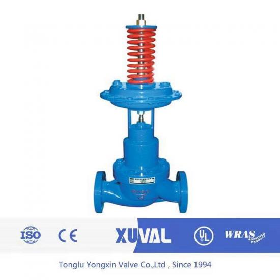
Summary: The direct acting self operated pressure (differential pressure) regulating valve (V230 self operated pressure regulating valve) is composed of valve body,valve seat,valve core and other parts.It is an energy-saving product that can automatically adjust the pressure only by the pressure change of the regulated medium without external energy.It can be used for pressure control of non corrosive (maximum temperature 350 ℃) liquid,gas,steam and other media It is widely used in petroleum,chemical industry,metallurgy,light industry and other industrial sectors as well as urban heating and heating system.
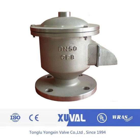
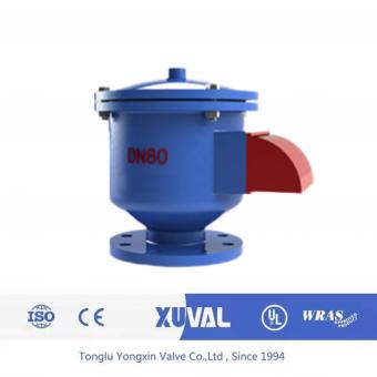
Introduction: ZFQ-1 explosion-proof fire-proof breathing valve produced by our company is a relatively new product in China. It is a new product with flame arrester and breathing valve. Its new structure is the first in China. It is a necessary safety equipment for petrochemical storage tank. Its biggest advantages are good fire resistance, stable suction performance, simple structure, light weight and convenient maintenance. The product is suitable for storage of class a oil with flash point lower than 28 ℃ and class B oil with flash point lower than 60 ℃, such as gasoline, kerosene, diesel oil, crude oil, toluene, ethanol, aromatics, sulfur and other media tanks. It works normally in the temperature environment of -35 ℃ -60 ℃.
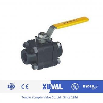
ZMBQ pneumatic film cutting valve adopts top guide structure, with multi spring actuator.It has the advantages of compact structure, light weight, sensitive action, S-streamline fluid channel, small pressure drop loss, large valve capacity, convenient disassembly and assembly, etc.
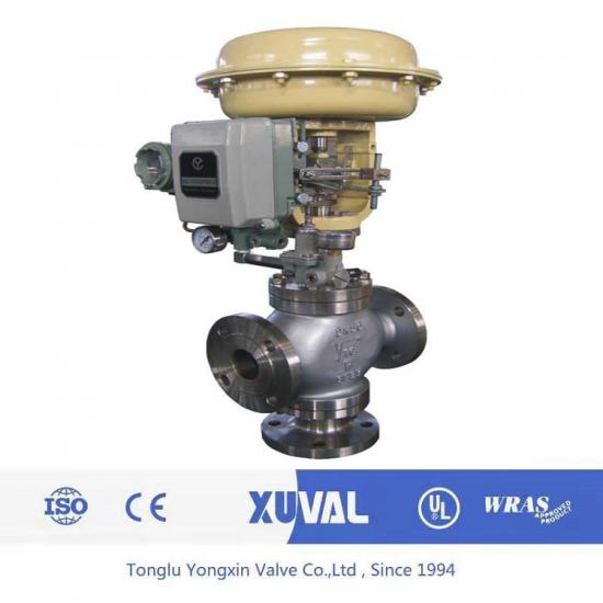
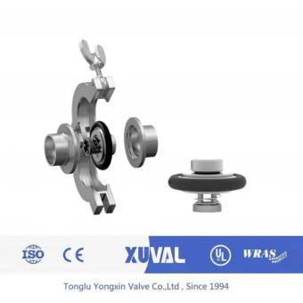
Overview of ZX pneumatic diaphragm three way control valve: ZX new series pneumatic diaphragm three-way control valve adopts cylindrical thin-wall window valve core guide,which is different from the bushing guide of plunger valve core.Equipped with multi spring actuator.ZX type pneumatic diaphragm control valve has the advantages of simple structure,light weight,small volume and convenient disassembly.Widely used in accurate control of gas,liquid and other media,process parameters such as pressure,flow,temperature,liquid level to maintain a given value.The utility model is suitable for the occasions where one fluid flows out in two paths through the three-way valve or two fluids are combined into one fluid through the three-way valve. This series of products have two kinds of three-way confluence (ZXQ) and three-way shunt (ZXX). The nominal pressure rating is 1.6, 4.0 and 6.4Mpa, and the diameter range of valve body is DN25-200. The applicable fluid temperature ranges from - 60℃ to + 450℃.The leakage standard is grade IV.There are two kinds of flow characteristics:straight line and parabola.
ZAZXE electric three-way regulating valve (sub) flow control valve using cylindrical thin-walled window spool guide.
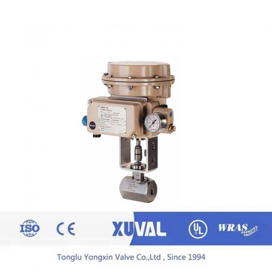
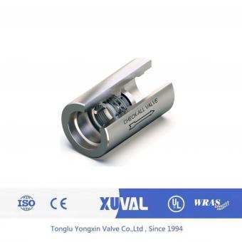
Small flow control valve is a special control valve for the control of small flow, can control the flow of all kinds of gas, liquid, steam, KV value up to 0.005.Therefore, it can be used in many occasions where accurate control of small flow rate is needed, such as laboratory test equipment, or industrial equipment in mass production, to control the small flow rate of chemicals, dyes, flavors and other additives.
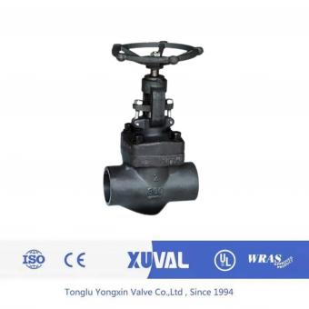
HAA ordinary Angle valve is a top guide structure of the regulating valve.The valve body structure is close together, the pressure drop loss is small, the flow is large, the adjustable range is wide, the flow characteristic accuracy is high, the dynamic stability is good, the valve core guides the area to be large, the vibration resistance is good.
Eccentric rotary valve is also called CAM deflection valve.
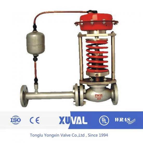
Product introduction: ZZY type self operated pressure regulating valve does not need additional energy. It uses the self energy of the regulated medium and the power source to introduce the actuator to control the position of the valve core, and changes the pressure difference and flow at both ends to stabilize the pressure in front of (or behind) the valve. It has the advantages of sensitive action, good sealing, low power of pressure set point wave and so on. It is widely used in the automatic control of pressure reduction and pressure stabilization of gas, liquid and steam medium.
For inquiries about our products or pricelist, please leave to us and we will be in touch within 24 hours.


 NO.139,Xianghe Road,Fangbu Industrial Zone,Tonglu,Hangzhou,China
Copyright © 2024 Tonglu Yongxin Valve Co.,Ltd.All Rights Reserved. Powered by dyyseo.com

IPv6 network supported


