

 English


Precautions for valve accessory selection - filter pressure reducing valve
The correct selection of valve accessories is of great significance for the reliable and stable operation of pneumatic valves. The control loop of the valve is composed of each accessory. Improper selection or failure of valve accessories can lead to abnormal or refusal of valve operation, posing a huge safety hazard to the process.

The compressed air output from the air compressor contains a large amount of pollutants such as water, oil, and dust. It is the killer of our pneumatic components.
Deteriorated oil forms tar like substances, leading to the deterioration and aging of rubber and plastic materials.
Moisture has a significant impact on pneumatic components: pipeline metal rusts, water freezes, lubricating oil deteriorates, and lubricating grease is washed away.
Rust and dust can cause relative wear of moving parts, accelerate damage to sealing components, and lead to air leakage.
A pressure reducing valve adjusts and reduces the higher inlet pressure to the outlet pressure that meets the requirements for use (pressure regulation). And ensure the stability (stabilization) of the outlet pressure after adjustment.
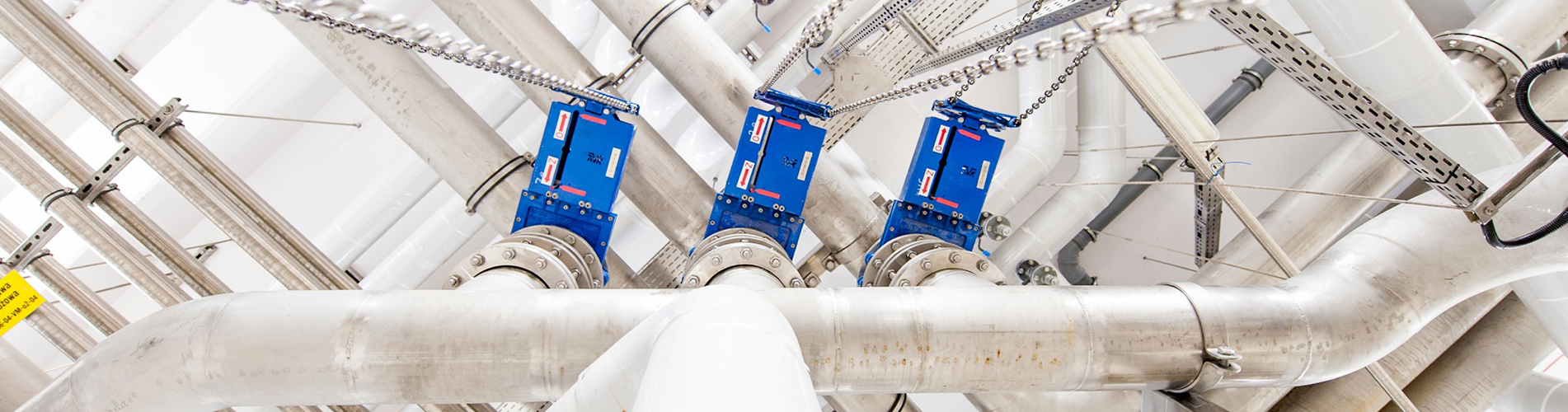
The front end of each pneumatic valve control circuit is equipped with a filtering and pressure reducing valve, which plays a role in filtering compressed air and reducing pressure and stabilizing pressure.
(1) Selection of usage environment
1.1 In places with direct sunlight, products made of all metal materials should be selected. If there are plastic or resin materials, they should be shielded from sunlight to avoid deterioration or temperature rise caused by UV radiation.
1.2 In places exposed to rain or dust, products with rain and dust prevention functions should be selected.
1.3 Surrounding areas with heat sources, poor ventilation (to prevent softening and damage caused by radiation heat, heat sources should be shielded).
1.4 In offshore environments, salt spray corrosion prevention treatment or the use of stainless steel materials should be considered.
1.5 In environments containing or adhering to organic solvents and chemicals, physical properties may deteriorate. In situations with the above factors or suspicious situations, metal cups should be used for safety reasons. The following table is for reference only. Please use it after experimental confirmation based on actual conditions.
1.6When used at low temperatures, the freezing of water can cause damage to the sealing components and poor operation, so measures to prevent freezing should be taken.
1.7Regularly inflate and deflate the pressure inside the standard cup of the filter pressure reducing valve to avoid damaging the cup body. In the above situations, it is recommended to use a metal cup.
In situations where leakage into the surrounding environment is not allowed or where fluids other than air are used, exhaust collectible products should be selected.
1.9 Confirm the "IN" and "OUT" markings on the inlet and outlet of compressed air, or connect after confirming the arrow direction. If reversed, it will cause misoperation.
The water cup of the 1.10 air filter pressure reducing valve should be installed vertically facing downwards to prevent poor drainage and secondary pollution of the gas source.
1.11 Space for maintenance and operation should be left on the top, bottom, and front of each product.
(2) Technical parameter selection
2.1 Using fluids. When using fluids other than compressed air, please contact the manufacturer for confirmation.
2.2 Operating temperature. The fluid temperature and ambient temperature are fixed. When used beyond the scope, it can cause damage, malfunction, and poor operation Usually, the ambient temperature range of the normal temperature type filter pressure reducing valve is -5~60 ℃; Low temperature type: -30~60 ℃; The special temperature type is -40~80 ℃.
2.3 Use pressure. Select the operating pressure of the filter pressure reducing valve based on the size of the gas source pressure. When used beyond the scope, it can cause damage, malfunction, and poor operation. The pressure resistance of a regular filter pressure reducing valve is 1.5 MPa, and the maximum operating pressure is 1.0 MPa. Special pressure ranges can be selected by contacting the manufacturer.
2.4 Set pressure. Select the appropriate set pressure range for the filter pressure reducing valve based on the allowable operating pressure of downstream equipment. The set pressure range of a regular filter pressure reducing valve is 0.05~0.85 MPa. Special pressure ranges can be selected by contacting the manufacturer.
2.5 Filtering accuracy. The standard filtration accuracy of the pressure reducing valve for instrument air source filtration is 5 μ M.
2.6 Connection diameter and flow characteristics. Calculate the required flow rate value of the circuit based on the volume and action speed of the pneumatic actuator. Select the corresponding filter pressure reducing valve and connecting pipe diameter according to the required flow rate value.
2.7 Drainage method. The drainage methods of filter pressure reducing valves are divided into automatic drainage type and manual drainage type. Usually, manual drainage is selected when assembled separately on the valve for use, and automatic drainage can be selected when assembled in a control cabinet. When used in low-temperature environments, automatic drainage type should not be selected.
(3) Working principle
3.1 Working principle of filters

Explanation of the working principle of the filter:
The compressed air flowing in from the inlet rotates strongly through the notch in the tangent direction of the guide plate. Liquid oil, water, and solid pollutants are centrifuged and thrown onto the inner wall of the water cup, then flow to the bottom. Compressed air, which removes liquid oil, water, and large particulate impurities, further removes small particles through a filter element and flows out from the outlet. The baffle can prevent the liquid oil and water in the lower part from being swept back into the airflow. The condensate accumulated in the water cup can be discharged from the drain by pressing the manual button.
Filter element: Sintered metal filter element is resistant to high/low temperature, washable, and has stable filtration performance. When there is too much sludge, it can be removed for cleaning and has high reusability. When the pressure difference between the inlet and outlet is greater than 0.1MPa, or when it has been used for more than 2 years. Please replace the filter element!
3.2 Working principle of pressure reducing valve

Explanation of the working principle of the pressure reducing valve:
Pull the handwheel outward and rotate it clockwise.
The regulating spring is compressed, pushing the diaphragm downwards, and the valve core is opened through the valve stem. The inlet air pressure is regulated by the valve core to reduce pressure, resulting in a pressure output.
The outlet pressure gas enters the lower chamber of the diaphragm through the feedback channel, generating an upward thrust on the diaphragm.
When the pressure at the lower part of the diaphragm and the spring force at the upper part are consistent (when the thrust and pressure regulating spring force are balanced), a stable air pressure is obtained at the outlet.
Categories
Recent Posts
For inquiries about our products or pricelist, please leave to us and we will be in touch within 24 hours.


 NO.139,Xianghe Road,Fangbu Industrial Zone,Tonglu,Hangzhou,China
Copyright © 2024 Tonglu Yongxin Valve Co.,Ltd.All Rights Reserved. Powered by dyyseo.com

IPv6 network supported


