

 English


How to use a pressure regulating valve to reduce delay in the analysis system?
How to use a pressure regulating valve to reduce delay in the analysis system?
The process measurement is real-time, but the analyzer response cannot be real-time. From sampling port to analysis
There is always a delay in the instrument. Unfortunately, this delay is often underestimated or misunderstood.
In the analysis sampling system, delay is defined as the time required for a new sample to travel to the analyzer.
What is the reason for the time delay? How to shorten the delay?
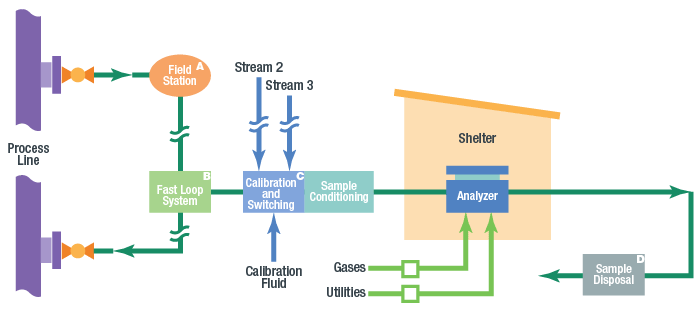
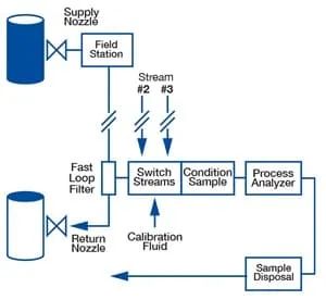
The delay within the sample system is a common cause of incorrect results in the process analyzer. The process measurement is real-time, while the analyzer response is not. There is always a delay from the sampling port to the analyzer. As shown in the figure below, there may be delays in the following parts of the analytical instrument (AI) system: process pipelines, sampling ports and probes, field stations, conveying pipelines, sample adjustment systems, flow switching systems, and analyzers.
It is important to understand that latency is cumulative. Time delay includes fluid from the process pipeline to the analyzer
The total time used, including the time required for the final analysis. For example, if it takes five minutes for a gas chromatograph to analyze a sample, then these five minutes must be added to the delay of the sample adjustment system and the flow switching system, as well as the delay of the conveying pipeline, on-site station, sampling port, and probe. Then, on the basis of the above time, the time required to travel from the process device where the fluid is being monitored to the sampling port must also be added. This is the total time required from the monitored process device to the calculated analyzer.
Unfortunately, this delay is often underestimated, or not taken into account or misunderstood. In many cases, analyzer experts and technicians often overlook this delay and focus on how to make the sample suitable for the analyzer. Analyzer experts may assume that the analysis measurements are real-time. However, sampling systems often fail to meet industry standards for one minute response time, creating ample opportunities for delays. Even for long cycle times, the delay should be minimized as much as possible. However, delays beyond industry standards may not necessarily bring problems. The process engineer must determine the acceptable delay based on the process dynamics.
When the delay exceeds the expected time of the system designer, it becomes a problem. Inaccurate estimation of time delay or incorrect assumptions can lead to poor process control. Understanding the causes of latency and learning to calculate or estimate latency within a reasonable error range can reduce latency and improve overall system responsiveness.
Reasonably arrange process pipelines, sampling ports, fast circuits, and conveying pipelines to achieve efficient implementation
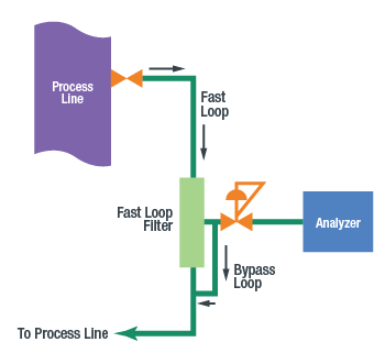
To reduce latency, the sampling port should usually be placed close to the analyzer, although this is not always feasible. The sampling port should be located upstream of delay sources such as barrels, tanks, dead corners, stagnant pipelines, redundant equipment, and outdated equipment (such equipment should be phased out to improve fluidity). In some cases, due to previously mentioned factors, it is not possible to specify the sampling port location near the process analyzer. If the distance between the sampling port and the analyzer is far, it is recommended to use a fast loop to improve the speed of fluid delivery to the analyzer. If designed properly, the flow rate in the fast loop will be much faster than the flow rate through the analyzer pipeline.
For gas samples, on-site workstations can be used to reduce the pressure in the conveying pipeline or fast circuit. At the same flow rate, the delay in the conveying pipeline decreases proportionally to the decrease in absolute pressure. When the pressure is reduced by half, the delay also decreases by half. The on-site workstation should be as close as possible to the sampling port. The earlier the time for blood pressure reduction, the better.
For liquid samples, it is not advisable to use adjustable on-site workstations. The liquid should be kept at high pressure to avoid the formation of bubbles. When the liquid sample needs to be converted into gas before analysis, a vaporization pressure regulating valve can be used at the on-site workstation. However, this will result in a considerable amount of latency. When a liquid is transformed into a gas, its volume will expand dramatically. The expansion rate depends on the molecular weight of the liquid.
Generally, the measured steam flow rate after the pressure regulating valve will be greater than 300 times the liquid flow rate before the vaporization pressure regulating valve. For example, when the steam flow rate is 500 cm3/min, the liquid flow rate may be lower than 2 cm3/min. Therefore, it takes 25 minutes for the liquid to flow through a 10 foot quarter inch sleeve. In order to shorten this period of time, we must reduce the volume of the sleeve in front of the pressure regulating valve. For example, when using a sleeve that is only one eighth of an inch long, the liquid can reach the pressure regulating valve in just 30 seconds. However, this time must also include the delay inside the probe. The thinner the probe, the faster the response
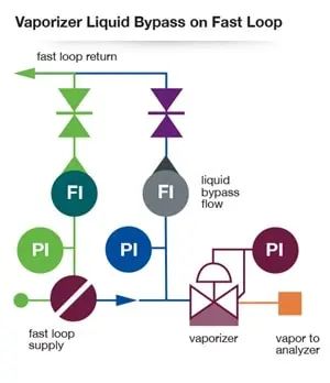
Another way to achieve faster response is to install the vaporization pressure regulating valve as close to the analyzer as possible. Install the pressure regulating valve after the fast circuit filter and use another liquid fast circuit to ensure positive flow before vaporizing the pressure regulating valve. The purpose of this design is to minimize the amount of slow liquid reaching the pressure regulating valve as much as possible.
Sample flow switching
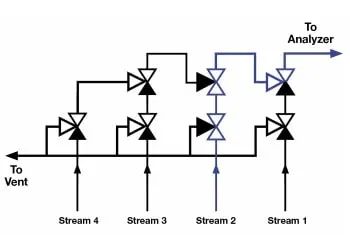
In order to avoid delays as much as possible, the sample flow switching component must run quickly and rinse the old samples quickly while delivering the new flow to the analyzer. The construction of dual shut-off and dual discharge (DBB) valves currently adopts traditional component or small modular design, which can provide sample flow switching with small dead angles and no cross flow pollution caused by valve leakage.
The traditional DBB adopts a serial DBB construction, as shown in the following figure. Series DBB eliminates dead corners by using a second shut-off valve instead of a T-connector.
How to use a pressure regulating valve to control time delay?
The pressure regulating valve can control the pressure, and the pressure in the analysis system is closely related to time. In a flow controlled gas system, the lower the pressure, the shorter the delay.
Any major part of the analytical instrument system may experience delays, including process pipelines, sampling ports and probes, on-site workstations, conveying pipelines, sample adjustment systems, sample flow switching systems, and analyzers. The following figure is an example of a typical process analyzer sampling system.
Delay is cumulative. The delay includes the total time required for the fluid to travel from the monitored process to the analyzer. Now, we will focus on the important role that on-site workstations and pressure regulating valves play in reducing delays.
Make the right choice of pressure regulating valve to reduce delay
Pressure regulating valve is an important tool for solving delay in analytical systems. The lower the pressure in the gas system, the faster the response time. Generally speaking, the earlier the gas system pressure decreases, the better. In the case of liquid evaporation, please consider using a liquid fast circuit to maintain liquid flow before the vaporization pressure regulating valve. On site workstations are one of the locations in complex analytical instrument systems that can significantly reduce latency, but the latency methods must always be comprehensive. To reduce latency, it is necessary to carefully study all possible causes of delay in the system.
Categories
Recent Posts
For inquiries about our products or pricelist, please leave to us and we will be in touch within 24 hours.


 NO.139,Xianghe Road,Fangbu Industrial Zone,Tonglu,Hangzhou,China
Copyright © 2024 Tonglu Yongxin Valve Co.,Ltd.All Rights Reserved. Powered by dyyseo.com

IPv6 network supported


